
A motor-control fault often starts with a gap in understanding, not a failed component. Industrial motor control training in the Philippines through Trilogix Institute covers the principles behind starting, stopping, reversing, protecting, and controlling the speed of electric motors. It also develops the ability to read wiring and ladder diagrams and understand operating and deceleration methods.
Knowing component names is useful, but understanding how they work together is what makes a motor circuit clear. This guide explains the core principles and skills to look for, from diagram interpretation and operating modes to speed control, starting methods, and deceleration. You’ll see how each topic relates to practical motor operation and how to assess whether a training program fits your learning goals.
Key Takeaways
- Learn how wiring diagrams and ladder diagrams represent motor-control circuits, and how reading them helps you follow control logic.
- Compare hand-off-automatic operation with sequence controls to understand how control choices shape motor operation.
- Explore how speed control and reversing affect motor behaviour and why the control method matters for the task.
- Understand the purpose of different motor starting and deceleration methods before choosing an approach for an application.
- Build a clear foundation in the principles of starting, stopping, speed control, reversing and motor protection.
Wiring diagrams and ladder diagrams
Industrial motor-control diagrams show how power components and control logic work together. Learning to read both formats helps connect a circuit’s intended operation with its physical wiring, whether you’re studying in the UAE or preparing for technical work.
Industrial Control Diagrams
An industrial control diagram maps the relationships among a motor, its control devices, and its power supply. A motor-starter circuit, for example, can show how a start command energizes a contactor and how a stop command interrupts that control path. Identify the components, then trace how each affects motor operation.
For learners in the UAE, diagram interpretation builds a practical foundation for understanding control circuits. Start by identifying the supply, control devices, and motor output. Then follow the path a start command takes through the circuit. Compare the diagram’s symbols and labels with the components used in a training exercise.
Wiring and Wire Diagrams
A wiring diagram focuses on physical connections: which terminal connects to which device, and how conductors link components. For example, a drawing might show the control supply passing through a stop pushbutton, then a start pushbutton, before reaching a contactor coil. Follow the sequence using terminal labels and wire paths.
Wiring diagrams translate circuit intent into connection points. Read from the supply connections through the control devices, then toward the load or coil. Check each symbol against its label and each conductor against its destination. This helps distinguish a device’s function from the physical route its wiring takes.
Ladder Diagram Logic
A ladder diagram presents control logic as horizontal rungs between two vertical rails. Each rung represents a logical path, with contacts determining whether an output, such as a motor contactor coil, can energize. Read each rung from left to right and identify the conditions that must be met for its output to operate.
A start-stop example makes the logic clear: the stop contact must allow the circuit to continue, while pressing start completes the path to the coil. A holding contact can keep the path active after the start button is released. Trace what changes in the diagram when each contact opens or closes.
Use both diagram types in a practical exercise. First, trace the ladder logic to understand the required sequence. Then follow the wiring diagram to locate the corresponding terminals and conductors. If the motor doesn’t respond as expected, compare the intended control path with the shown connections. This builds a disciplined approach to circuit interpretation, rather than reliance on component names alone.
For a focused review, identify the supply, control devices, output, and motor in each drawing. Then explain how a start command changes the logic and where that command travels through the wiring. These steps make diagram reading a practical skill for understanding motor-control circuits and preparing for technical work in the UAE.
Hand-off-automatic and sequence controls
Hand-off-automatic control lets an operator choose between manual commands and automatic operation. Sequence control, by contrast, advances equipment through planned stages. Understanding both helps learners interpret how a motor responds to an operator, a control signal, or a process condition.
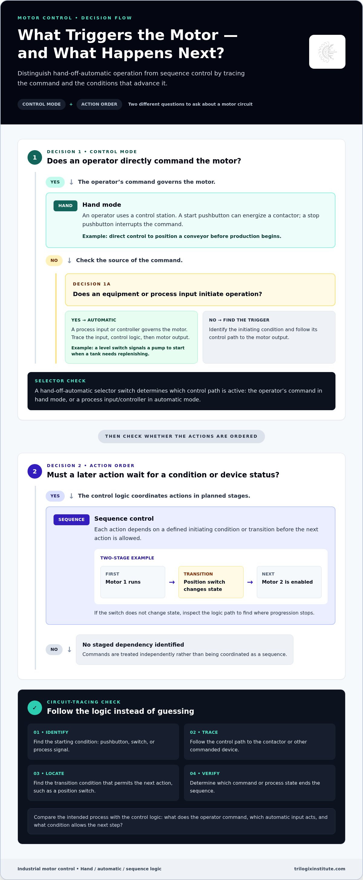
In hand mode, an operator directly commands a motor through a control station. For example, pressing a start pushbutton can energize a contactor, while a stop pushbutton interrupts the command. This mode suits tasks where a person needs direct control, such as positioning a conveyor before production begins. The control circuit still determines how each command reaches the motor.
Automatic mode uses an input from equipment or a process to initiate operation. A level switch, for example, can signal a pump to start when a tank needs replenishing. Trace the input, control logic, and motor output in that order. This reveals which condition starts operation and which signal stops or changes it.
A hand-off-automatic selector switch determines which control path is active. In hand mode, the operator’s command governs the motor; in automatic mode, a process input or controller does. Compare both paths on a control diagram: identify the selector position, follow the active contacts, and note how the motor output changes between modes.
Sequence controls coordinate multiple actions rather than treating each motor command independently. In a basic conveyor process, one motor may need to start before another is allowed to run. The control logic can use a limit switch or another device’s status as a condition for the next step. Identify each initiating condition, output, and transition in the sequence.
- Identify the starting condition: Find the pushbutton, switch, or process signal that begins the sequence.
- Trace the first output: Follow the control path to the contactor or other commanded device.
- Find the transition condition: Locate the signal that permits the next action, such as a position switch.
- Follow the stop condition: Determine which command or process state ends the sequence.
In a two-stage example, a first motor can run until a position switch changes state, then enable a second motor. If the switch doesn’t change, inspect the logic path to identify where progression stops. This offers a structured way to analyse sequence behaviour without guessing at the cause.
When studying hand-off-automatic and sequence controls, compare the intended process with the control logic. Ask what the operator commands, which automatic input acts, and what condition allows the next step. These checks clarify how control modes and ordered actions shape motor operation in industrial systems.
Motor speed control and reversing
Motor speed control changes how quickly a motor drives its load. Reversing changes its direction of rotation. Training in the UAE can connect each function to the control method and operating requirements of a particular motor application.
Training should address safe isolation, protective devices, grounding, and applicable electrical regulations in the UAE. Learners can consider how these subjects affect circuit design and safe work practices, rather than relying on a regulation name without practical context.
A variable-frequency drive (VFD) controls an AC motor’s speed by adjusting the electrical supply frequency. This is useful when a process requires speed variation, such as changing a conveyor’s movement. Connect the speed command to the drive’s output, then consider how the driven load responds as speed changes.
Other control arrangements suit different motor designs and operating needs. A training exercise can compare a fixed-speed motor circuit with one using a VFD, then identify what changes in the control path. The key question is whether the required speed adjustment belongs in the motor-control design or the process itself.
- Identify the motor and load: A conveyor and a pump may have different operating demands.
- Define the speed requirement: Decide whether the application needs one speed or adjustable operation.
- Trace the command: Follow how an operator or process input reaches the control device.
- Observe the response: Relate the control output to the motor’s direction and driven load.
Reversing a three-phase motor commonly involves changing the phase sequence supplied to it. A forward-reverse control arrangement uses separate contactors to select direction. Electrical and mechanical interlocks prevent both contactors from closing together, which would create an unsafe circuit condition. Identify the forward path, reverse path, and interlocks on the control diagram.
Direction control also depends on the machine’s task. A hoist, conveyor, or positioning mechanism may require forward and reverse commands, but the sequence and stopping behaviour can differ. Training should connect the direction command to the equipment’s operating logic, including how an operator selects direction and how the circuit prevents conflicting commands.
In a practical exercise, first identify the motor type and required operating range. Next, trace the speed or direction command through its control devices. Then explain what changes at the motor when the command changes. This helps distinguish speed adjustment from reversing, two functions that may share control components but serve different purposes.
Motor starting and deceleration methods
A motor’s starting method shapes how it accelerates and interacts with its load. Deceleration determines how it slows after a stop command. Compare these methods through circuit examples, then connect each choice to the motor and driven equipment.
Direct-on-line (DOL) starting connects a motor directly to its supply through a switching device. It offers a straightforward control arrangement for a suitable application. Trace how a start command energizes the contactor and how the motor receives power. Also consider whether the machine can tolerate the abrupt start.
Star-delta starting uses a different connection during acceleration, then changes to a running configuration. Compared with DOL, it can reduce starting current but also reduces starting torque. Motor and load suitability are therefore essential. Follow the switching sequence and identify when the circuit changes from star to delta.
A soft starter controls the voltage supplied during motor acceleration. It can help achieve a smoother start, but it isn’t a continuous speed-control device. In a conveyor example, compare its acceleration behaviour with DOL. Identify the control command and explain how the starter changes the motor’s start.
A variable-frequency drive (VFD) controls motor speed by adjusting supply frequency. Its programmed acceleration and deceleration ramps can shape both starting and stopping. In a pump example, trace how a speed command changes during a ramp. Distinguish this method from a soft starter’s role during acceleration.
Stopping methods differ. A coast stop removes the motor’s drive, allowing the load to slow naturally. A controlled ramp uses a VFD to reduce speed over a planned interval. Dynamic braking applies braking action to slow the motor, while regenerative braking can return energy through compatible drive equipment. The right method depends on the application and stopping requirement.
- Define the load: A fan, pump, or conveyor creates different starting and stopping demands.
- Compare acceleration: Review how DOL, star-delta, soft starters, and VFDs affect startup.
- Choose a stopping response: Contrast coast, ramp, and braking methods for the task.
- Trace the control sequence: Follow the command from input through the starter or drive.
For a practical comparison, consider a loaded conveyor that must start smoothly and stop at a defined process point. Assess whether a soft starter addresses the startup needs, then consider whether a VFD-controlled ramp better suits both acceleration and deceleration. Justify the method based on load behaviour and control requirements, rather than selecting equipment by name alone.
Industrial motor control principles
Industrial motor control brings together the actions that govern a motor’s operation. Electric motors convert electrical energy into rotational mechanical energy. Control methods manage how that energy is applied, adjusted, and stopped in equipment.
Core principles include starting, stopping, speed control, reversing, and protecting electric motors. Each has a practical purpose. A conveyor may need a controlled start, adjustable speed, and a stop command; a pump may require a different operating sequence. Effective learning connects each principle to the motor, its load, and its control circuit.
Protection is part of the control system, not an afterthought. Understand how protective devices relate to the motor circuit and what the control system does when a fault occurs. For example, tracing the control path helps distinguish a normal stop command from an interruption caused by a protective device.
Are industrial motor control courses in the Philippines TESDA-accredited or certified? The Industrial Motor Control program prepares learners for TESDA Electrical Installation & Maintenance EIM NCIII National Certification. Preparation for a national certification is distinct from claiming that the course itself is accredited or that completion automatically grants certification.
How long do courses take, and what schedules are available? Course duration depends on the principles covered and the time devoted to practical circuit work. Schedules depend on the training format and how instruction and equipment-based practice are arranged.
What are the prerequisites for enrolling? Requirements depend on the course level and learning objectives. A beginner course introduces motor-control concepts, while learners with electrical knowledge may be ready to build on existing skills.
Which Philippine cities offer in-person training? Trilogix Institute delivers training through its Philippines campus. Practical learning includes access to motor-control equipment, where components such as contactors and protective devices support exercises in tracing and understanding circuits.
Are online or hybrid courses available in the Philippines? Delivery formats vary. Online instruction can present theory and diagram-reading concepts, while hands-on work requires access to motor-control equipment; a hybrid format can combine those learning activities.
Assess a course by following one motor through its operating cycle. Identify its start command, normal stop, speed-control method, and protective response. Then explain how the circuit changes when the motor reverses or encounters a fault. This approach tests understanding of connected principles, rather than memorization of isolated component names.
For a structured introduction to these concepts, explore motor-control course options and compare how the course scope supports your technical learning goals.
Trilogix Institute: TTI Dubai Foundation Electrical Engineering
Trilogix Institute offers TITP Beginner Essential Industrial Motor Control for learners building practical knowledge of motor-control fundamentals. Its instructor-guided training combines lecture with hands-on exercises using live equipment, connecting the diagrams, operating modes, and control methods covered in this guide.
For broader electrical foundations, TTI Dubai Foundation Electrical Engineering provides a related learning pathway. Choose based on your starting point: focus on essential motor-control concepts or develop a wider electrical engineering foundation. These courses support skill development, but they aren’t university degrees or job-placement guarantees.
Explore the course options and choose a learning path that fits your goals by visiting trilogixinstitute.com or contacting Trilogix Institute.
Turn your technical interest into a learning plan
Match your goals with the level of instruction you need. If you’re considering industrial motor control training in the Philippines, decide whether you want to build a technical foundation, strengthen practical understanding, or progress toward broader electrical learning. A clear goal helps you choose a course that suits your direction.
Trilogix Institute offers TTI Dubai Foundation Electrical Engineering, TTI Dubai Professional Culinary Arts, and TTI Dubai Advanced AutoCad 2D & 3D. For a technical path, focus on the electrical engineering option and the motor-control learning discussed in this guide. Different goals call for different learning paths, so keep your priorities at the centre of the decision.
Take the next step at a pace that suits your plans. Contact Trilogix Institute to explore your learning direction and move forward with confidence.
Frequently Asked Questions
What industrial motor control training courses are available in the Philippines?
Options include beginner motor-control instruction and broader industrial automation study. Trilogix Institute offers TITP Beginner Essential Industrial Motor Control for learners starting with foundational control skills, alongside its Industrial Automation Specialization for a wider technical focus. Compare course scope with your current experience and intended applications. If you’re new to the field, a beginner course can establish a foundation before you progress to more integrated automation topics.
Which schools and training centers offer industrial motor control training in the Philippines?
Trilogix Institute provides technical training through its Philippines campus, including TITP Beginner Essential Industrial Motor Control. When comparing courses, consider whether instruction is instructor-led and includes practical equipment access, not only classroom explanation. For example, exercises using industrial control equipment can connect concepts with real components and project-based tasks. Trilogix Institute’s hands-on training uses live equipment and projects that simulate field and plant environments.
What topics and hands-on skills are covered in industrial motor control courses?
Courses combine motor-control theory with equipment-based practice. Learners develop skills in interpreting control circuits, identifying components, and applying control concepts through instructor-guided exercises and individual practical activities. A practical task might involve assembling a training circuit from a diagram, then explaining how its components interact. Trilogix Institute’s hands-on training uses live equipment and project-based learning to connect classroom concepts with simulated field or plant environments.


