

A precise drawing does more than show an idea; it helps a project team turn that idea into work they can build, review, or produce. A practical AutoCAD designer job description centers on creating and revising technical drawings, layouts, and 3D models in response to project requirements. The role also involves coordinating with engineers, architects, and other team members so the drawings reflect the design accurately.
It’s easy to assume the job is simply operating CAD software. In practice, designers also organize documentation, interpret design information, and update drawings carefully when project details change. Understanding these responsibilities can help you decide whether the role suits your strengths and identify skills to develop.
This guide explains the core duties, the CAD tools used, and the drawing types and documentation an AutoCAD designer may produce. It also outlines how practical training in AutoCAD 2D and 3D can build relevant skills for pursuing this work in the UAE.
Key Takeaways
- Understand how designers turn project concepts into technical drawings and update them as requirements change.
- See where 2D drafting and 3D modelling fit into an AutoCAD designer’s workflow.
- Learn how organized drawing files and project documentation support clear team communication.
- Recognize how detail drawings, assembly drawings, layouts, and models serve different project needs.
- Explore how practical AutoCAD 2D and 3D training can help you build relevant drafting skills.
AutoCAD drafter/designer role overview
An AutoCAD designer creates technical drawings and models from project requirements using computer-aided design software. In the UAE, the role connects an engineer’s or architect’s concept to clear documentation that project teams can review, revise, and use.
A CAD drafter translates design information into precise drawings, while a CAD technician typically prepares, edits, and organizes CAD files. An AutoCAD designer may handle both drafting and broader design development, but job titles and duties vary by employer and sector.
Typical responsibilities span the project workflow. A designer gathers structural and material requirements, attends design discussions, and turns agreed concepts into drawings. They may calculate estimated dimensions, create layouts or 3D views, and update designs when project changes or site conditions require revisions. They also present work to team members and incorporate their feedback.
Accuracy is only one part of the job. Designers organize files, meet drawing-submission deadlines, and ensure drawings follow project guidelines and relevant industry standards. For example, an architect may request a layout revision, while an engineer may clarify a dimension before the drawing advances.
Qualifications depend on the employer and the work involved. Job descriptions commonly request a diploma or degree in drafting, engineering, architecture, or a related field; some specify a bachelor’s degree. AutoCAD certification or a related credential may be preferred, but there is no single UAE requirement for every role.
For Dubai and Abu Dhabi roles, common requirements include AutoCAD proficiency, knowledge of drafting principles and symbols, and the ability to interpret technical information. Employers may also seek clear communication, teamwork, careful file management, and experience producing 2D or 3D drawings. Sector knowledge can matter: a construction role may emphasize building drawings, while a manufacturing position may focus on product designs.
AutoCAD design is primarily computer-based, so sustained screen and desk work make an ergonomic setup and regular movement practical considerations. Site visits or coordination in active work areas can involve different hazards; follow the employer’s safety procedures and site instructions.
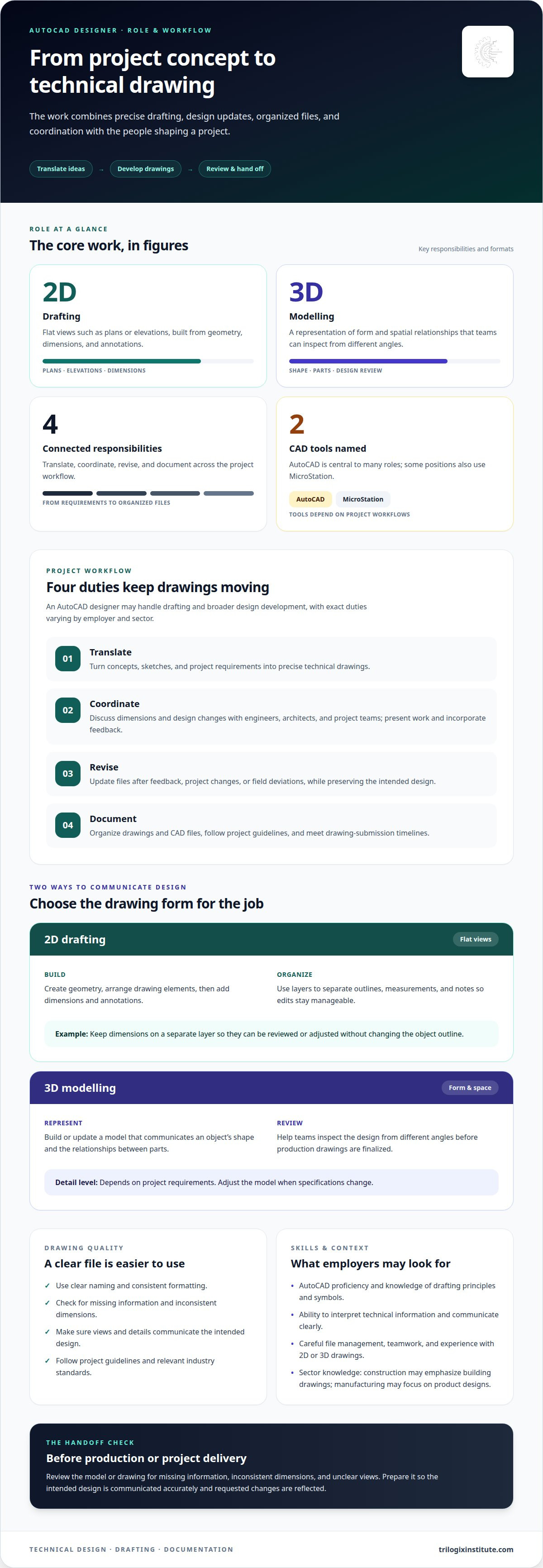
- Translate: Convert concepts, sketches, and project requirements into technical drawings.
- Coordinate: Discuss dimensions and design changes with engineers, architects, and project teams.
- Revise: Update files after feedback, project changes, or field deviations.
- Document: Maintain organized drawings and submit them according to project timelines.
A useful AutoCAD designer job description separates core duties from employer-specific qualifications. This helps applicants see whether a role prioritizes drafting accuracy, design input, coordination, or a mix of responsibilities.
Professionals at organizations like Trilogix Institute emphasize that designers must coordinate daily details with engineers and architects, translating conceptual designs into technical drawings and visualizing concepts from 2D to 3D. They must revise drawings in response to client feedback and project changes, including updates to construction designs that reflect changes and deviations in the field. Keeping work aligned with project deadlines and timelines for drawing submissions ensures that drawings comply with industry standards, regulations, and project guidelines. Together, these tasks support coordinated, up-to-date project documentation throughout design and construction.
CAD software use
Computer-aided design (CAD) software lets designers create and edit technical drawings digitally. In AutoCAD, a designer can develop a drawing from project information, revise its geometry, and prepare a model for production. Proficiency means more than knowing commands; it means choosing accurate methods for the drawing’s purpose.
AutoCAD supports both two-dimensional (2D) drafting and three-dimensional (3D) modelling. A 2D drawing represents objects through flat views, such as plans or elevations. A 3D model represents form and spatial relationships, helping teams inspect a design from different angles. Some roles focus mainly on 2D documentation, while others require both capabilities.
In a 2D workflow, the designer creates geometry, arranges drawing elements, and adds dimensions and annotations. Layers help separate information, such as outlines, measurements, and notes, so edits remain organized. For example, placing dimensions on a separate layer makes them easier to review or adjust without changing the object’s outline. Clear naming and consistent formatting also help colleagues interpret the file.
In 3D modelling, the designer builds or updates a model that communicates an object’s shape and relationships between parts. A model can support design review before production drawings are finalized. The designer checks that its views and details communicate the intended form, then adjusts the model as specifications change. The level of detail depends on the project’s requirements.
AutoCAD is the main tool named in many designer roles, but some positions also use MicroStation, CAD software for preparing and maintaining engineering drawings. The software an employer specifies often depends on project workflows and existing files. Designers who switch between programs need to understand the drawing requirements, not just rely on familiar commands.
Production readiness means completing and preparing an AutoCAD model for manufacturing or project delivery. Before handoff, the designer checks for missing information, inconsistent dimensions, and unclear views. They also preserve the intended design while applying requested changes. This final review helps prevent avoidable confusion during production.
When assessing software skills, distinguish command familiarity from usable results. A capable designer can explain how they created a drawing, organized its information, and revised it after feedback. A portfolio example can show the process: the original requirement, how the CAD file developed, and the finished drawing or model. This gives employers a clearer picture of practical ability.
For those building these skills, structured practice in AutoCAD 2D and 3D can develop command fluency and drawing judgment together. The strongest preparation connects each software operation to a clear project purpose, from setting up geometry to preparing a model for production.
Design documentation
Design documentation is the organized record of a project’s drawings and supporting information. It helps engineers, architects, and production teams interpret design intent and track revisions. An AutoCAD designer may maintain drawing files, sketches, specification sheets, and related documents. For example, a revised component drawing belongs with the project files, not as an isolated working copy.
A drawing register is an index that identifies project drawings and their current status. It keeps files accessible and helps distinguish drafts from updated versions. A clear file name can identify the project, component, drawing type, and revision. When a team member requests a change, the designer can locate the right file and update its record.
Supporting documents explain details that a drawing alone may not communicate. A specification sheet records relevant design data, while a user manual explains how a product or system is used. AutoCAD designers may compile data sheets, prepare rough sketches, and update manuals alongside design files. For a custom fixture, a sketch can capture the initial concept before it develops into a precise technical drawing.
- Collect: Review project information, sketches, and blueprints during design discussions.
- Organize: Save drawings and supporting files in a consistent project structure.
- Update: Revise the relevant drawing and documents after approved design changes.
- File: Retain completed designs for future reference and team coordination.
Reviewing documentation means checking that a drawing communicates fit, form, and function. Fit concerns how parts relate or connect; form describes their shape; function addresses their intended purpose. For example, a custom tool drawing should give the team enough information to understand its geometry and operation. Designers also compare drawings with company requirements and project guidelines before handoff.
Standards and symbols provide a shared language for technical drawings. Mechanical design roles may prefer familiarity with ASME and ISO standards, while P&ID documentation requires knowledge of relevant standards and practices. A P&ID, or piping and instrumentation diagram, represents process equipment and its connections. Conventions depend on the discipline and project; consistent symbols help readers interpret drawings correctly.
Timely updates matter when a design changes. A designer should revise the affected drawing, update its supporting specification or manual, and maintain the current project record. For example, if a component dimension changes, related documents should not retain the earlier value. Coordinated updates keep the drawing package aligned and give colleagues a dependable basis for review, production, or future reference.
Record-keeping extends beyond the drawings themselves: AutoCAD drafters organize and maintain drawing files and project documentation, then file designs for future reference. They may prepare rough product sketches and review sketches and blueprints in meetings, so the working record reflects the material discussed. Documentation duties can also include creating user manuals and updating other documents on time. Before completion, designers may review engineering drawings and supporting documents for compliance with company or industry design standards and for fit, form, and function.
Detail and assembly drawings
A detail drawing describes one component clearly enough for review or production. It focuses on a single part, such as a bracket, rather than the complete product. AutoCAD designers use views and annotations to communicate its shape and dimensions. The required detail depends on the design and the project team’s needs. The drawing should make the component understandable without relying on an unexplained sketch.
An assembly drawing shows how multiple components fit together as a complete unit. It helps reviewers understand the relationships between parts and how the design is arranged. For example, a machine assembly drawing can show a housing alongside the components fitted within it. Unlike a detail drawing, which explains an individual part, an assembly drawing presents the overall arrangement.
Designers may produce both drawing types for one project. The detail drawing clarifies each required component, while the assembly drawing shows how the components fit together. Teams can review an individual part without losing sight of its place in the overall design. Clear references between drawings connect component information to the assembly view.
GD&T, or geometric dimensioning and tolerancing, describes dimensional and geometric requirements on engineering drawings. Familiarity with its fundamentals can help designers interpret how a part’s geometry should be communicated. ASME print reading is also relevant to some roles. These skills support clear technical communication, but drawing requirements still depend on the project and its applicable standards.
Revision work is another core task. When a design changes, the designer updates existing drawings to reflect the current design. A change to one component may also affect its assembly view. For example, if a part’s shape changes, the detail drawing needs revision and the assembly drawing may need an updated representation. Coordinating both views helps prevent conflicting information in the drawing package.
A focused review can catch issues before a drawing reaches the next project stage. Designers can compare detail and assembly views, check that annotations are legible, and confirm revisions appear consistently. They can also check the drawing against project guidelines and relevant design standards. This helps engineers, production teams, and other reviewers interpret the information accurately.
- Detail drawing: Communicate one component’s geometry and required design information.
- Assembly drawing: Show how components relate within the complete unit.
- Revision: Update affected views when a design changes.
- Drawing review: Check clarity, consistency, and alignment with project requirements.
In an AutoCAD designer role, preparing and revising both drawing types connects CAD work to practical project communication. Each view should serve its purpose, whether explaining a component or showing how parts fit together.
Equipment layouts and 3D models
An equipment layout shows how equipment is arranged within a project space. It turns spatial requirements into a drawing that teams can review. In a facility plan, for example, the layout can show equipment positions and how they relate to the surrounding area. The designer develops the drawing from project information and revises it when requirements change.
A 3D model is a digital representation of an object or space with depth, width, and height. It helps a team visualize a concept beyond a flat drawing. AutoCAD designers may create 3D engineering drawings to communicate a proposed form and support design review. A model can make spatial relationships easier to understand before teams proceed with related work.
Layouts and models serve different purposes. A 2D equipment layout communicates arrangement from a selected view, while a 3D model helps show form from different angles. Teams may use both to discuss a design: the layout explains where equipment sits, and the model illustrates its shape and position in context. The required drawing type depends on what the project team needs to understand.
To develop a useful layout, the designer starts with the available project requirements and identifies the equipment to show. They arrange the information so the equipment and its relationship to the space remain clear. If project details change, the designer revises the affected layout. For example, a change in equipment positioning should appear in the drawing that communicates the arrangement.
Model development follows a related sequence. The designer translates the available design information into a 3D representation, reviews whether it conveys the intended form, and updates it after feedback. A model is only useful when it reflects the current design information. The designer therefore needs to distinguish a visual concept from a finalized drawing intended for production.
Before sharing either output, review its purpose and clarity. A layout should make the arrangement easy to interpret; a model should communicate the form and spatial relationships relevant to the review. The designer can also check the output against project guidelines and drawing requirements. Clear presentation helps engineers, architects, and other team members give focused feedback.
- Layout: Show equipment positions in relation to the project space.
- 3D model: Represent form and spatial relationships in three dimensions.
- Review: Confirm the output communicates the design purpose clearly.
- Revision: Update affected views when project information changes.
For aspiring designers, practicing both 2D layouts and 3D models develops complementary skills. A useful exercise is to represent one design through a flat arrangement drawing and a three-dimensional view, then assess what each communicates. This builds judgment about selecting the right drawing type for a project task.
Trilogix Institute: TTI Dubai Advanced AutoCad 2D & 3D
Trilogix Institute’s TTI Dubai Advanced AutoCad 2D & 3D is a practical next step for learners building CAD skills for design work. The hands-on technical course focuses on AutoCAD 2D and 3D, areas used to produce technical drawings and models. It can suit people preparing for drafting tasks or strengthening their ability to work with digital designs.
Choose this training if you want structured, practical development rather than relying only on independent practice. It supports learning related to the drawing types and CAD workflows discussed here, while job requirements still vary by employer and role.
To discuss the course, contact Trilogix Institute.
Build Your Next Step in CAD
Use an AutoCAD designer job description to guide your professional development, not simply as a list of hiring criteria. Identify the skills you want to strengthen, then choose a focused practice project to demonstrate your progress. A clear portfolio can show how you approach a design brief, organize your work, and respond to feedback. Make each example easy to understand, with a brief explanation of its purpose and your contribution.
As your skills develop, match your learning to the kind of work you want to pursue. Trilogix Institute’s TTI Dubai Advanced AutoCad 2D & 3D offers a relevant training path for learners building practical CAD capability. For guidance on whether it aligns with your goals, contact Trilogix Institute to learn more.
Career progress comes from deliberate practice and clear evidence of your skills. Choose a skill to develop, apply it in a project, and keep building with purpose.
Frequently Asked Questions
What does an AutoCAD designer do on a typical workday?
An AutoCAD designer typically alternates between focused drawing work and coordination with project colleagues. A day might start with a new design brief, followed by creating or adjusting a drawing in response to comments. The designer may clarify an unclear dimension with an engineer, prepare files for review, and prioritize the next task based on its submission deadline.
What are the key responsibilities of an AutoCAD designer?
Key responsibilities include turning project requirements into usable CAD outputs and keeping them aligned with team decisions. After a review meeting, for example, the designer may receive marked-up comments, identify the affected views, and revise the relevant files. The role also requires clear communication about design questions so unresolved details do not cause confusion at later project stages.
Which AutoCAD and technical skills do employers expect?
Employers commonly expect confident AutoCAD use, sound drafting judgment, and the ability to interpret technical instructions. Candidates can explain how they approach a practical task, such as turning a sketch into a clear drawing or applying review comments without changing unrelated details. Communication and attention to detail matter too: designers need to understand feedback, ask precise questions, and present work colleagues can assess.


